Project demo
This demo guides you through setting up a simple scenario where there are two Debian devices connected through an Ethernet cable and there are two containers on each device, communicating through the Ethernet cable. By using our software components, you can shape the traffic of the first device remotely from the second device.
Basic setup
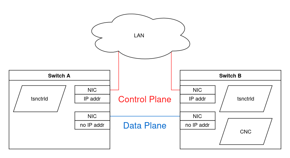
For the best reproducibility, install Debian 13.1 fresh on two computers and connect them directly with an Ethernet cable. This Ethernet cable will be on the data plane, where the network traffic is travelling through.
Also take two more cables to connect both devices to your LAN. Your LAN will act as the control plane.
From here on out, we will call one of the devices switch A and the other switch B. Decide now which is which.
On both switches, run
ip address showto view the network connections. The network interfaces of both the control plane and the data plane have to be UP on both switches (Hint:sudo ip link set <NIC> up). Also write down the names of both switches’ data plane NICs (network interface cards, e.g. “eth0” or “enp2s0f2”).If the switches don’t have an IP address on the control plane yet, assign one to each now. Either way, write down their control plane IP addresses. Don’t give them IP addresses on the data plane! If there are any, they will be automatically removed later.
Install the
tsnctrldas described here on both switches.Install the CNC as described here only on switch B.
Install Docker on both switches as described here.
Creating the scenario
We will now run two Docker containers in interactive mode on each device and connect them into a TSN network.
Then we will have them send traffic to each other and create a scenario where a less important application steals the bandwith of a more important application.
Afterwards we will solve this problem with our tsnctrld and CNC software components!
Open three terminals on each switch. From here on out terminals A1, A2, and A3 are on switch A and terminals B1, B2, and B3 are on switch B.
Terminal
Location
Purpose
A1
Switch A
Switch A control
A2
Switch A
Send important traffic to B2
A3
Switch A
Send unimportant traffic to B3
B1
Switch B
Switch B control
B2
Switch B
Receive important traffic from A2
B3
Switch B
Receive unimportant traffic from A3
In both terminals A1 and B1 navigate to root of the project repository you downloaded in the first step during installation.
Build our demo docker image on both switches
# A1 & B1:
sudo docker build -t tsnctrld-demo tools/project_demo/
Run 4 docker containers in interactive mode. We set the container names to
demo1anddemo2, make sure a container’s name length doesn’t exceed 9 characters!# A2 & B2: sudo docker run --rm -it --network=none --name demo1 tsnctrld-demo # A3 & B3: sudo docker run --rm -it --network=none --name demo2 tsnctrld-demo
We’ll use bash scripts to automate the virtual wiring of the docker containers. Make sure the wiring scripts are all executable by running:
# A1 & B1:
find ./tools/virtual_wiring/ -type f -iname "*.sh" -exec chmod +x {} \;
Create virtual bridges on each switch and connect them to the data plane NIC of the switch
# A1:
sudo ./tools/virtual_wiring/vbridge_create.sh <DATA-PLANE-NIC>
# B1:
sudo ./tools/virtual_wiring/vbridge_create.sh <DATA-PLANE-NIC>
Connect all 4 docker containers to the virtual bridge on their switch and also assign an IP address to them. Keep in mind that once a docker container stops, the connection is broken and once you start it again you must use the script again to connect it:
# A1:
sudo ./tools/virtual_wiring/container_link.sh demo1 172.29.253.1/24
sudo ./tools/virtual_wiring/container_link.sh demo2 172.29.253.2/24
# B1:
sudo ./tools/virtual_wiring/container_link.sh demo1 172.29.253.3/24
sudo ./tools/virtual_wiring/container_link.sh demo2 172.29.253.4/24
Now start the scenario! Container
demo1on switch A (terminal A2) will send important traffic to containerdemo1on switch B (terminal B2). Let’s start with sending 1 datagram per second and the SKB priority is 3.# B2: ./traffic_sink # A2: ./traffic_source 172.29.253.3 1400 1 3
You should now see how on B2 the datagrams from A2 are received. Let’s try to max out the bandwith between the switches: Increase the datagrams/sec value to 50.000 and see whether B2 can receive almost all of them. If it does, double the rate until you reach the maximum throughput limit and write that approximate limit down.
# A2:
./traffic_source 172.29.253.3 1400 <DATAGRAMS-PER-SEC> 3
Multiply the maximum throughput with 0.6 and now run both containers on that amount of traffic. Also set the second container’s SKB priority to 2 instead, it is less important
# A2:
./traffic_source 172.29.253.3 1400 <60-PERC-OF-MAX> 3
# B3:
./traffic_sink
# A3:
./traffic_source 172.29.253.4 1400 <60-PERC-OF-MAX> 2
B2 and B3 combined now send more traffic than the link can support. You should observe that both B2 and B3 receive about the same amount of traffic, even though B2 should have priority!
Schedule modification
We will now use tmux to launch our software components in separate sessions.
Remember:
To create a new session: tmux new -s <SESSION-NAME>
To exit from a session without terminating: Ctr+B then D
To reattach to a running session: tmux attach -t <SESSION-NAME>
To list all running sessions: tmux ls
Launch the TSN control daemon on both switches, but make switch A the gPTP grandmaster of your TSN network. There should be only one grandmaster per network!
# A1 (separate tmux session):
sudo tsnctrld --nic <SWITCH-A-DATAPLANE-NIC> --grandmaster --ntp
# B1 (separate tmux session):
sudo tsnctrld --nic <SWITCH-B-DATAPLANE-NIC>
Then on both exit with out terminating with
Ctr+BthenD. Both switches are now able to receive instructions via NETCONF!Launch the CNC on switch B, use a separate tmux session again:
# B1 (separate tmux session):
sudo cncd
Create a file
schedule.jsonon switch B (terminal B1), leaving more time for SKB priority 3 to send in the gate control list:{ "host_name": "vstsn01", "interfaces": [{ "name": "enp2s0f2", "bridge_port": { "gate_parameter_table": { "gate_enabled": true, "admin_gate_states": 255, "admin_cycle_time_extension_ns": 500, "admin_cycle_time": { "numerator": 1200000, "denominator": 1000000000 }, "admin_base_time": { "seconds": "0", "nanoseconds": 0 }, "admin_control_list": [{ "index": 0, "operation_name": "sched:set-gate-states", "gate_states_value": 65, "time_interval_value": 100000 }, { "index": 1, "operation_name": "sched:set-gate-states", "gate_states_value": 16, "time_interval_value": 1000000 }, { "index": 2, "operation_name": "sched:set-gate-states", "gate_states_value": 32, "time_interval_value": 100000 } ] } } } ] }
And feed that schedule into the CNC interface:
# B1
sudo cnc_cli set-schedule --gap=hold schedule.json
You should now observe that the more important traffic gets more bandwith (terminal B2), while the less important traffic gets restricted (terminal B3)!